The PiDP-11 is a hardware front end to a Raspberry Pi running simh. The blinkenlights interface translates the keys and LEDs to the Raspberry Pi GPIO pins.
With the Raspberry Pi and simh software you can run a whole range of operating systems from the PDP-11 including UNIX V5, V6, V7, System III System V and 2.11 BSD and many more. You select which OS to boot by setting the keys.
While this is a lot of fun, it is still a simulation, which just isn't the same. The Raspberry Pi takes about a minute to boot before the LEDs come alive. I wanted a PDP-11 in silicon.
To the rescue is Sytse van Slooten's PDP2011 a recreation of the PDP-11 using FPGA technology. In essencence, this is a recreation of the PDP-11 hardware in VHDL. Since VHDL is not specific to a particular FPGA, there are a number of FPGA boards you can use.
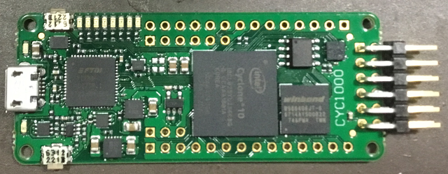
The CYC1000 is a tiny development board combining an Intel Cyclone 10 LP FPGA with an FTDI USB interface, 64 Mbit of SDRAM, 16 Mbit of flash memory and an Arrow USB Programmer2 to run the whole thing. It measures 25mm by 61mm, about the same size as the Adafruit Feather boards and costs about the same as a Raspberry Pi ($39 for Arrow).
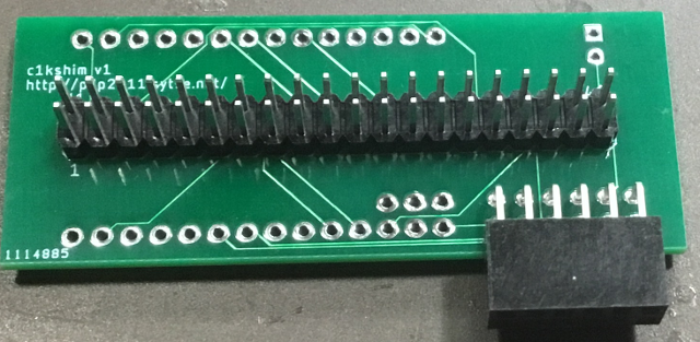
The CYC1000 pinout must be adapted to the Raspberry Pi 40 pin header for which the PiDP was designed. To this end Sytse designed a shim to rearrange the CYC1000 pins to match that of the Raspberry Pi. The CYC1000 has enough pins to drive the PiDP-11 and three PMOD interfaces. This allows support for a serial console, an SD card pretending to be a disk drive and an ethernet port.
The ideal OS for this configuration is 2.11 BSD. Dating to the early 1990s, it represents the most modern version of UNIX for the PDP-11. It supports IPv4 and allows you to telnet, rlogin and rsh to run code across the network and transfer files with ftp and rcp. It also supports the vi editor if your ed skills are a bit rusty. It has a K&R C compiler, a FORTRAN-77 compiler and a Pascal interpreter.
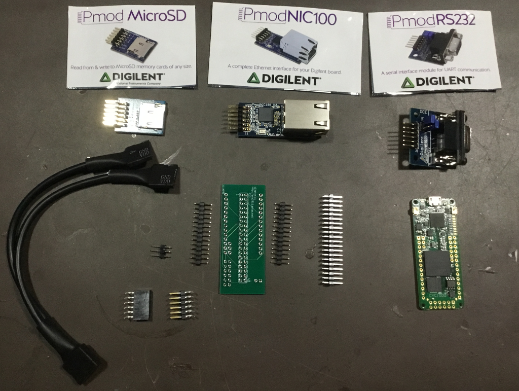
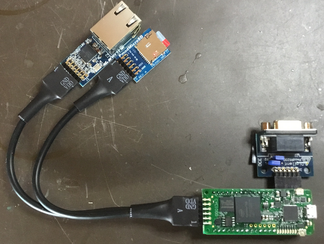
This image shows all the items you need:
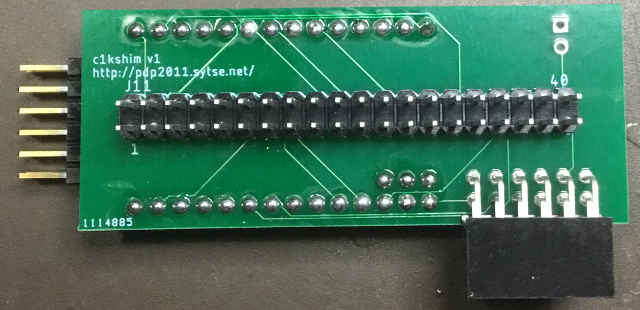
Solder the 2x20 pin header onto the shim. It goes on the same side as the writing, long side of the pins facing away from the PCB.
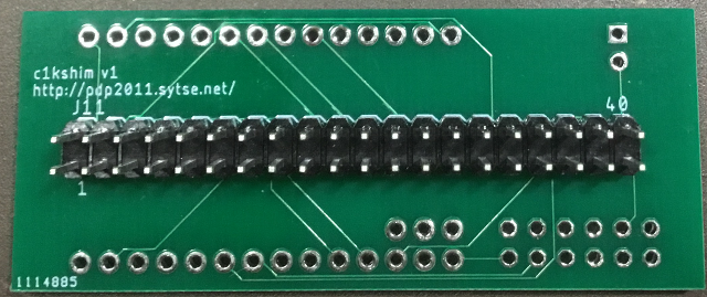
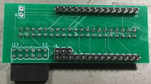
Solder a 2x6 90 degree female header on the same side as the 2x20 as shown. This will make the 2x6 upside down but the pins are cross-connected, so if you put the device in right side up all is well. You will only be using one row, but using a 2x6 adds mechanical stability.
Solder a 2x6 90 degree header on the CYC1000. I used a male because this connects to the splitter cable which is a female but can connect to a female header using a 2x6 male-male adapter. Since I will only use this with the splitter cable I eliminated the 2x6 male-male adapter by doing a male header instead.
Add two 1x14 and one 1x3 header to the shim and solder the CYC1000 and shim together. Note that the spacing is pretty tight, so make sure you trim the headers such that they don't short out on the next board.
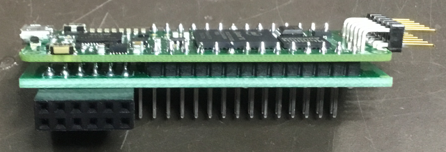
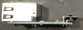
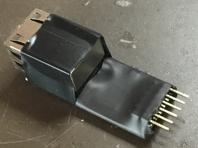
The pins stuck out a long way on the shim side, so what I did was to dry fit the CYC1000 to the shim, solder the CYC1000 to the header, clip off the long pins flush with the shim, and then solder the shim to the header. That makes for a neat package shown from below here.
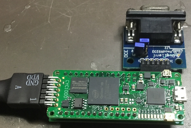
This is how the splitter cable and PmodRS232 serial adapter connects to the package. The polarity of the cable matters, Writing should be on the upper side.
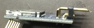
The PmodNIC100 and PmodMicroSD has a 2x6 pinout, but only the upper 6 pins are used. To reduce the danger of shorting, I clipped the lower row of pins.
Here is the whole setup. On the 1x6 side of the splitter cable the A version must be the PmodMicroSD. The PmodNIC100 goes on the other connector. Polarity matters - the writing should be on the top side.
The PmodNIC100 will be used as a dongle. To avoid shorts, I put 3/4 inch shrink wrap over the circuitry and and electric tape over the connector to cover all the contacts.
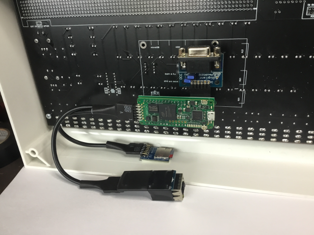
Here is the whole thing mounted on the PiDP-11. The PmodMicroSD is attached inside the case with double sided tape. I also added electric tape on the bottom of the PmodRS232 to prevent shorts with the PiDP-11 circuit board even though there is a significant amount of clearance. The PmodNIC100 is a dongle that can be brought out of the case.
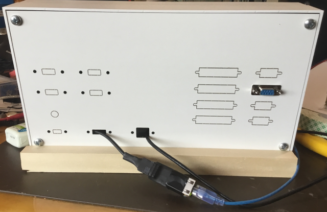
Back of the PiDP11, showing the USB cable for power and console, the ethernet dongle, and DB-9 bringing the PmodRS232 out. For the serial connection I wired up only pins 2, 3 and 5 (data send, data receive and ground).
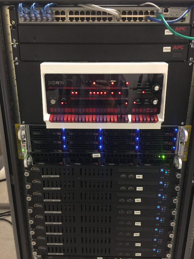
Installed in the rack using a 4U blank.